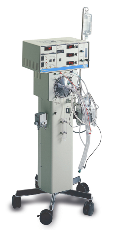
VIASYS
3100 A HFOV
3100 A HFOV is HFOV personal plane for the high-power "NA"ÉVÉČÄÖ respiratory failure treatment of the piston drive system by the linear motor.
Because the patient circuit is "DEISUPO"-a basket, the maintenance is easy and there is not a decline of the operating rate by the sterilization in it.
2. The
performance
1) The mode that it is possible to use
HFOV
2) This proximal dater
The bias flow rate .0-40
LPM
The HFO number of times
.3-15Hz
The HFO mean-pressure .3-45
cmH2O
The HFO output āóP> Above
90cmH2O
3. The explanation of the control
circuit, the controlling
mechanism
1) The outline of the controlling mechanism
It has the pressure pressure relief valve which is special respectively to the limit pressure, the average airway pressure, the dump pressure and it is controlling it in ironhand "WO" being safe and the sureness of it.
2) The characteristic of the mechanical mechanism
Including the HFO occurrence part, the patient circuit becomes disposable.
3) The gas flow rate measurement
It isn't possible to measure.
4) The intake valve and the expiration valve
It doesn't exist.
The HFO developmental-mechanics becomes a music speaker and similar structure.
It is driven by the magnetic force which occurs to the permanent magnet and the electric coil.
A coil is hung into the permanent magnet using spiders.
With this structure, the operation which doesn't have friction becomes possible and it has the operation lifetime of equal to or more than 4,000 hours.
The electric coil is driven by Square wave driver and drives the piston which connects with the coil to the direction of + and the direction of -.
The drive distance of the piston is decided by the frequency of counterforce, square wave to the piston coil which is made with the breathing circuit pressure which touches the plate of the size and the piston with the anode/the cathode voltage which is added to the electric coil and Piston Centering (the central-ization of the piston) dial.
The output voltage of Square wave driver is controlled by electronic control and power control of the alarm system.
The position of the electric coil and the piston is decided by the potential of the square wave which is added to the electric coil.
The position of the electric coil according to the change of the potential, too, changes but transit time (the time which the movement takes the electric coil from the maximum movement position of the + position to the maximum movement position of the - position) which the displacement takes is a millisecond unit.
Therefore, when the frequency of "OSIRE-SIYON" is low, it stands still in the maximum movement position of the + position or the - position in most time.
On the other hand, when the frequency of "OSIRE-SIYON" increases, the ratio which transit time accounts for becomes big.
When the frequency increases more, in transit time, the electric coil can move to the maximum movement position, passes away and consequently, the amplitude of vibration of the piston decreases.
Because the electric coil generates much heat, a cooling system by high-pressure air is laid down.
The compressed air of 50psig (3.5 atm) is controlled by the air in 15L/the minute after decompressed by the regulator.
The air amplifier applies air in 60L/the minute around the electric coil at 45L/the total of capturing in the minute in the air indoors by the Jet Venturi effect.
In case of the overheat (equal to or more than 190üŗC) by doing the bad of the cooling system, the thermal cut circuit makes an oscillator stop.
The yellow LED lights up when the coil overheats (about 175üŗC).
The gas that an oxygen concentration was controlled by the blender is decompressed with regulators PR-4 and PR-1 and is controlled in the bias flow rate in Bias Flow Adjust.
As for this gas, the HFO generator which flows in to the patient circuit as Fresh Gas via the heating humidifier is connected with the patient circuit on the side of intake.
With the pressure relief valve which decides the upper limit of the mean-pressure, this drive gas is controlled in PR-2, Adj.Flow Restrictor ōÖ by Limit Valve.
Control Valve is the pressure relief valve which controls an average airway pressure.
This drive gas is controlled in PR-3, Adj.Flow Restrictor ōÖ.
Dump Valve is the relief valve which releases a patient circuit in the big worrying at the time of the abnormal fluid pressure.
PR-6 is purge diversion for the proximal airway pressure monitor line.
The flow of PR-5 and Air Amplifier is for the cooling of HFO developmental-mechanics.
5. The control
software
The explanation of the each function
Because it is HFO personal plane, there are not a special feature and a mode,
software and so on. The trigger feature, too, doesn't exist.
6. The operation
system
1)
Operating panel : 1;BIAS FLOW, 2;MEAN PRESSURE ADJUST, 3;MEAN PRESSURE LIMIT, 4;Power/āó of basic guideline ( figure ; 3100HFOV
P, 5;%Inspiratory Time, 6;Frequency, 7;Start/Stop, 8;MEAN AIRWAY PRESSURE, 9;Set Max Paw, 10;set Min Paw, 11;Paw>50cmH2O, 12;Paw<20% of "Set Max Paw", 13;Powe
r Fail, 14;Reset/Power Fail, 15a;Battery Low, 15b;Source Gas Low, 16;Oscillator
Overheated, 17;Oscillator Stopped, 18;45sec Silence, 19;PATIENT CIRCUIT SILENCE)
The setting of a mean-pressure and āóP is important.
Besides, there is a setting which is a bias flow, the center centering-control, the frequency, the % intake time, the oxygen concentration of the piston only.
A way of being established by the setting should consult because there is not it but it is as follows according to the guideline which Dr.Robert deLemons of Wilford Hall Medical Center(Lackland Airforce Base, Texas) created.
2) The setting of a mean-pressure
A mean-pressure is controlled in controlling the pressure of the balloon of Control Valve on the patient circuit side of the expiration.
Generally, oxygenation ability at the lung is roughly influenced by the setting of a mean-pressure.
To improve oxygenation ability, too, when doing a mean-pressure roughly tends.
3)āóP
āóP is the amplitude of vibration of HFO but specifically, it is the control which controls the drive electric current of the electromagnetic coil.
āóP has an influence on the emission of CO2 roughly.
Also, the attenuation by the tracheal tube is big.
For example, when the compliance is 1ml/cmH2O at 15 Hz, at the 2.5-mm tube, 34% and the attenuation by the tracheal tube can not be ignored at 47%, 6.5 mm at 60%, 5.5 mm at 80%, 4.5 mm at 90%, 3.5 mm.
Also, the bigger the frequency is, a tendency with the bigger attenuation there is.
Therefore, when PaCO2 can not be controlled, in the situation that the margin-of-safety can not be secured, next, the frequency must be lowered because it raises āóP but āóP has the upper limit on the safety.
In the last, it raises % intake time.
4) The bias flow
Generally, 10-15LPM is recommended by the premature baby, 10-20LPM is recommended by the newborn baby, 15-25LPM is recommended by the small child and 20-30LPM is recommended by the big child.
Generally, to set to rather many is safe if there is anxiety because there are few evils with too big flow rate.
5) The piston mid-gear control
It is controlling the mid-gear of the piston in controlling the base voltage of the square wave which is given to the electromagnetic coil.
However, if not being in the condition which is operating in the limited performance, generally, there are few influences in this setting.
6) The frequency
15-20 Hz are generally made valid by the premature baby and the newborn baby. At
the infant, 6-10 Hz become a standard.
6) The % intake time
It is displaying drive time in 1 cycle of the square wave which drives a piston in the %.
Because the temporal leeway passes away relatively with the movement of the piston when the frequency increases, (when the frequency is big,) the amplitude of vibration becomes bigger, increasing % intake time.
33% is general.
When PaCO2 can not be controlled even if it lowers a frequency, there is a hand to increase % intake time as the last way.
7. The monitor, the alarm
function
1) The alarm
There are a mean-pressure upper limit, a mean-pressure minimum, an airway pressure, "NADONO" alarm.
2) The monitor
A piston position is displayed by the LED bargraph. When the piston mid-gear isn't appropriate, it
commands with the manual.
(3) Equipment's
being
mal-function
There are to be power failure, a distributed-gas pressure malfunction, a battery, heating of HFO generator, "NADONO" alarm.
8. The display feature
The expired volume per minute can not be measured. There is not a graphic display. The position of the piston can be
monitored by the change of the LED bargraph.
It was shown in the figure. Note is necessary so as not to make a
mistake in the connection because it is complicated so often.
10. The daily maintenance
1) The patient circuit
It drains regularly from the watered lap.
2) The patient circuit calibration
"The patient circuit calibration" is the control mechanism to have decided the upper limit so as not for any more mean-pressure to be added to the respiratory tract whichever "REBERUN" "the adjustment of the mean-pressure" becomes.
It controls the screw of the main unit right surface for the airway pressure to become a place around 40cmH2O after raising MEAN PRESSURE LIMIT and ADJUST to the most size.
11. The regular
inspection
It receives regular inspection every 2,000 hours, or 6 months, 6,000 hours, or 3, 12,000 hours or 6 years.
12. The fault
1) There is much consumption of gas. It is
necessary to gas for the cooling.
2) The compensation to secure safety but the patient circuit is too complicated.
3) There are too many items to set. Because it is not an experimental unit, it
should delete an unnecessary item.
4) The lump that the mechanism is analog If electrolyzing a controlling mechanism, it
seems to have become the easier operation system.